
Red Hat OpenShift sandboxed containers (OSC) is based on the upstream Kata Containers open source project. OSC provides an additional isolation layer for pods by leveraging virtualization technologies. OSC provides the following capabilities:
- Protects the host from malicious workloads running in the pods (intentionally or unintentionally) by isolating the pod with another virtual machine (VM) layer.
- Protects the workload from other workloads leveraging the same VM isolation.
Peer-pods is a technology that extends OSC from a bare-metal deployment (based on QEMU/KVM) to deployments on a public cloud (AWS, Azure, IBM cloud, etc.) and third party hypervisors (such as VMware). Note that peer-pods can also be used with libvirt. This occurs when Red Hat OpenShift runs over QEMU/KVM VMs, and the OSC/peer-pods will also use those tools (through libvirt) to create VMs. We emphasize this point since part of the results we show later on assume this deployment model.
This blog will compare the deployments, configurations, and resources used for OSC/bare-metal vs. OSC/peer-pods.
Deployment comparison
The OSC/bare-metal solution only applies to OpenShift nodes running on bare-metal servers and not to OpenShift nodes running on VMs. The reason is that attempting to run the OSC/bare-metal solution on the latter would require nested virtualization (running a VM inside a VM), which is not supported in production by Red Hat. Many public clouds also don't support nested virtualization.
Thus, in OSC/bare-metal, the OpenShift worker nodes run on bare-metal servers, and the OSC workloads are deployed inside VMs that themselves also run on bare metal.
OSC/peer-pods technology extends OSC/bare-metal to be deployed on OpenShift nodes that are themselves running as VMs. It does this by creating a "peer VM," which is a VM created at the same level of virtualization as the OpenShift node VM (instead of nested) and seamlessly connected to the node VM. This results in the OpenShift node thinking that the OSC workload is local (just another namespace in the worker node) when, in practice, that workload is deployed on a separate VM altogether.
Both OSC/bare-metal and OSC/peer-pods deployments create a VM per pod:
|
OSC/bare-metal |
OSC/peer-pods |
|
|
Deployment |
Bare metal only (using QEMU/KVM for managing the VM) |
Public cloud or third party hypervisor (using their VM management APIs) |
Components comparison
The main components of OSC/bare-metal are different from those used with OSC/peer-pods:
|
OSC/bare-metal |
OSC/peer-pods |
Note |
|
|
Overall architecture |
Version 2.0 (Go) Version 3.0 (Rust) |
||
|
Container manager |
cri-o |
||
|
Runtime |
|||
|
Agent |
kata-agent |
||
|
Hypervisor |
QEMU/KVM |
Depends on cloud provider |
|
|
Cloud API adaptor |
No |
Implements the remote hypervisor support |
|
|
Agent protocol forwarder |
No |
Relays commands to the agent |
The main difference between OSC/bare-metal and OSC/peer-pods is different runtime components. The runtime components are selected by the runtime class through the runtimeClassName in the YAML file:
- runtimeClassName: kata # For OSC/bare-metal
- runtimeClassName: kata-remote # For OSC/peer-pods
To boot OSC/bare-metal pods, users need to define runtimeClassName as kata.
To boot OSC/peer-pods pods, users need to define runtimeClassName as kata-remote.
Virtualization comparison
The following table shows the differences in CPU, memory, storage, network, and disk images between the virtualization for OSC/bare-metal and OSC/peer-pods.
|
OSC/bare-metal |
OSC/peer-pods |
|
|
CPU |
CPU resources are dynamically managed. CPUs required by containers will be hotplugged to the pod VM. |
Fixed configuration that depends on cloud provider instance type, which defines the instance size. |
|
Memory |
Memory resources are dynamically managed. Memory required by containers will be hotplugged to the pod VM. |
Fixed configuration that depends on cloud provider instance type, which defines the instance size. |
|
Storage |
Virtio-fs is used for container rootfs, volumes, etc. |
|
|
Network |
Veth pair + Tap + Virtual network device + TC filter + Bridge |
Veth pair + VXLAN + TC filter + Bridge |
|
Guest image |
A VM image containing the same kernel as the host and the necessary initrd is transparently built when booting the host. As a result, in OSC/bare-metal, the guest kernel is always the same as the host kernel. |
A full disk image (such as qcow2) must be provided that contains the required kernel and initrd. In the long term, the necessary images should be provided by Red Hat. |
Note: Hotplug means enabling or disabling devices while a virtual machine is running.
- CPU hotplug allows the kata runtime to add virtual CPUs to a running VM without having to reboot it.
- Memory hotplug allows the kata runtime to add memory to a running VM without having to reboot it.
Hotplug is useful because, in Kubernetes, the containers, not the pods, define the CPU and memory requirements, making it difficult to size the VM correctly at creation time when only pod-related information is available.
CPU analysis
With OSC/bare-metal, the default number of vCPUs is one. It's defined by option default_vcpus in the /usr/share/kata-containers/defaults/configuration.toml. Before starting a container, the Kata runtime reads the default_vcpus option and starts the VM with the default value.
You can request more CPU resources if the default single CPU is not sufficient for the container workloads. There are two methods you can choose:
- Specify CPU request/limit to request more CPU resources: After the VM startup, the requested CPUs will be hotplugged to the VM and be available inside the containers. However, the hotplugged vCPUs kata solution currently contains two bugs: one bug resulting in not all the hotplugged vCPUs coming online inside the containers, and the other bug causing interrupts not being balanced across the CPUs that have been added.
- Use the io.katacontainers.config.hypervisor.default_vcpus annotation to change the default vCPU number for a specific pod so that the corresponding VM will boot with the changed vCPU number.
With OSC/peer-pods, the number of CPUs depends on the cloud provider setup and currently cannot be changed after the VM boots.
- In the case of OSC/peer-pods deployed using libvirt, the default CPU is two, which is not changeable currently.
- For the Azure cloud, the default value can be defined by AZURE_INSTANCE_SIZE in the peer-pods-cm ConfigMap.
- For the AWS cloud, the default value can be defined by PODVM_INSTANCE_TYPES in the peer-pods-cm ConfigMap.
The cloud instance will start with the preset values. CPU hotplug is not supported in this situation.
The following is an example of the peer-pods-cm ConfigMap for Azure. It indicates the AZURE_INSTANCE_SIZE as Standard_D8as_v5, which is an Azure VM with eight vCPUs and 32G of RAM (see Azure VM comparison).
---
apiVersion: v1
kind: ConfigMap
metadata:
  name: peer-pods-cm
  namespace: openshift-sandboxed-containers-operator
data:
  CLOUD_PROVIDER: azure
  VXLAN_PORT: "9000"
  AZURE_INSTANCE_SIZE: Standard_D8as_v5
  AZURE_SUBNET_ID: ${AZURE_SUBNET_ID}
  AZURE_NSG_ID: ${AZURE_NSG_ID}
  AZURE_IMAGE_ID: ${AZURE_IMAGE_ID}
  PROXY_TIMEOUT: 5m
  DISABLECVM: "true"
Memory analysis
With OSC/bare-metal, the default size of memory is 2G. It's defined by option default_memory in the /usr/share/kata-containers/defaults/configuration.toml. Before starting a container, the Kata runtime reads the default_memory option and starts the VM with the default value.
You can request more memory resources if the default 2G is not sufficient for the container workloads. There are two methods to choose from:
- Specify memory request/limit to request more memory resources. After the VM starts, the requested memory will be hotplugged to it and available inside the containers.
- Use the io.katacontainers.config.hypervisor.default_memory annotation to change the default VM memory size so the VM boots with the changed memory size.
The following is an example of a YAML file to set the CPU/memory request/limit. It requests an extra two CPUs and an extra 4G of memory on top of the default one vCPUs and 2G of memory. In total, the pod will contain three vCPUs and 6G of memory:
---
apiVersion: v1
kind: Pod
metadata:
  name: buildah-kata
spec:
  runtimeClassName: kata
  containers:
    - name: buildah-kata
      image: quay.io/buildah/stable:v1.29.1
      command:
        - sleep
        - infinity
      securityContext:
        privileged: false
        allowPrivilegeEscalation: false
        runAsNonRoot: true
        runAsUser: 1001
        capabilities:
          drop:
            - ALL
        seccompProfile:
          type: RuntimeDefault
      resources:
        limits:
          cpu: "2"
          memory: "4Gi"
        requests:
          cpu: "2"
          memory: "4Gi"
The following is an example of a YAML file to change the default CPU and memory by annotations. It temporarily changes the default vCPUs to two and default memory to 4G. The pod VM will boot with eight vCPUs and 16G of memory:
---
apiVersion: v1
kind: Pod
metadata:
  name: buildah-kata-annotation
  annotations:
    io.katacontainers.config.hypervisor.default_vcpus: "8"
    io.katacontainers.config.hypervisor.default_memory: "16384"
spec:
  runtimeClassName: kata
  containers:
    - name: buildah-kata-annotation
      image: quay.io/buildah/stable:v1.29.1
      command:
        - sleep
        - infinity
      securityContext:
        privileged: false
        allowPrivilegeEscalation: false
        runAsNonRoot: true
        runAsUser: 1001
        capabilities:
          drop:
            - ALL
        seccompProfile:
          type: RuntimeDefault
With OSC/peer-pods, the default value of memory depends on the cloud provider setup:
- For the libvirt provider case, the default memory is 8G, which is not currently changeable.
- For the Azure cloud, the default value can be defined by AZURE_INSTANCE_SIZE in the peer-pods-cm ConfigMap.
- For the AWS cloud, the default value can be defined by PODVM_INSTANCE_TYPES in the peer-pods-cm ConfigMap.
The cloud instance will start with the preset value, and memory hotplug is not supported in this situation.
Storage analysis
On OSC/bare-metal, virtio-fs can be used to share container volumes, secrets, config-maps, configuration files (hostname, hosts, resolv.conf), and the container rootfs from the host file system to the guest. Virtio-fs is a shared file system designed specifically to let the host share directories with virtual machines. Since it is not a remote file system, it offers local file system semantics and good performance.
The following are a few examples for OSC/bare-metal. OSC/bare-metal supports many types of persistent volume plugins in OpenShift. Compared to ordinary OpenShift workloads, the OSC/bare-metal workloads use virtio-fs to present the local file system of the worker nodes to the pod VM. Remote volumes mounted to the worker node will also be mounted to the same path inside the pod VM. In the examples below, NFS and iSCSI are two types of network storage, and hostPath is local storage.
Storage NFS volumes
Persistent volumes (PVs) and persistent volume claims (PVCs) provide a convenient method for sharing a volume across a project. Below are the steps to provision one NFS volume for the pod.
First, define a PersistentVolume object with the NFS server and path:
---
apiVersion: v1
kind: PersistentVolume
metadata:
  name: nfs-pv
spec:
  capacity:
    storage: 2048Gi
  accessModes:
    - ReadWriteOnce
  nfs:
    path: /home/shared
    server: $nfs_server_ip
  persistentVolumeReclaimPolicy: Retain
Then create a PersistentVolumeClaim, which binds to the PVL:
---
apiVersion: v1
kind: PersistentVolumeClaim
metadata:
  name: nfs-claim1
spec:
  accessModes:
    - ReadWriteOnce
  resources:
    requests:
      storage: 1024Gi
  volumeName: nfs-pv
  storageClassName: ""
Next, start a pod with the PVC:
---
apiVersion: v1
kind: Pod
metadata:
  labels:
    run: busybox
  name: test
spec:
  containers:
    - image: quay.io/prometheus/busybox
      name: busybox
      securityContext:
        privileged: false
        allowPrivilegeEscalation: false
        runAsNonRoot: true
        runAsUser: 1001
        capabilities:
          drop:
            - ALL
        seccompProfile:
          type: RuntimeDefault
      volumeMounts:
        - mountPath: /my-nfs-data
          name: nfs-volume
  dnsPolicy: ClusterFirst
  restartPolicy: Never
  runtimeClassName: kata
  volumes:
    - name: nfs-volume
      persistentVolumeClaim:
        claimName: nfs-claim1
You can see the nfs directory is mounted at /my-nfs-data when you log in to the container, which runs inside the pod VM:
# oc rsh test /bin/sh
~ $ df -h
Filesystem            Size  Used Available Use% Mounted on
none                278.3G 16.4G 261.9G   6% /
tmpfs                64.0M     0 64.0M   0% /dev
tmpfs               952.4M     0 952.4M   0% /sys/fs/cgroup
shm                 952.4M     0 952.4M   0% /dev/shm
kataShared           23.4G 51.3M 23.3G   0% /etc/resolv.conf
kataShared           23.4G 51.3M 23.3G   0% /etc/hostname
kataShared          278.3G 16.4G 261.9G   6% /run/.containerenv
kataShared           23.4G 51.3M 23.3G   0% /etc/passwd
none                  2.1T 60.7G  2.0T   3% /my-nfs-data
kataShared          278.3G 16.4G 261.9G   6% /etc/hosts
kataShared          278.3G 16.4G 261.9G   6% /dev/termination-log
kataShared           23.4G 51.3M 23.3G   0% /run/secrets
none                 45.6G 20.0K 45.6G   0% /var/run/secrets/kubernetes.io/serviceaccount
tmpfs                64.0M     0 64.0M   0% /proc/kcore
tmpfs                64.0M     0 64.0M   0% /proc/keys
tmpfs                64.0M     0 64.0M   0% /proc/timer_list
tmpfs                64.0M     0 64.0M   0% /proc/sched_debug
If you read the "source" in the virtio-fs daemon on the worker node, you can see it indicates the shared directory between the worker node and the pod VM:
[core@worker0 ~]$ ps aux | grep virtiofs

root 1050334  0.0  0.0 122804  4792 ?    Sl   05:50   0:00 /usr/libexec/virtiofsd --syslog -o cache=auto -o no_posix_lock -o source=/run/kata-containers/shared/sandboxes/b252777daf6ac319036811198469fd22dfa056b850e51c8ecd3cab20fd720716/shared --fd=3 -f --thread-pool-size=1 -o announce_submounts
Next, check the virtio-fs shared directory on the worker node. Here are all the files and directories, and you can see the nfs mount my-nfs-data:
[core@worker0 ~]$ sudo ls /run/kata-containers/shared/sandboxes/b252777daf6ac319036811198469fd22dfa056b850e51c8ecd3cab20fd720716/shared
91ff9ffa738c578cf77a9502290eda1c34b66ec70fdaf158ec506309c6baad26
91ff9ffa738c578cf77a9502290eda1c34b66ec70fdaf158ec506309c6baad26-3a956a7e4de9ba05-passwd
91ff9ffa738c578cf77a9502290eda1c34b66ec70fdaf158ec506309c6baad26-5a7b6b44d145d24c-serviceaccount
91ff9ffa738c578cf77a9502290eda1c34b66ec70fdaf158ec506309c6baad26-7612209629c3fb02-my-nfs-data
91ff9ffa738c578cf77a9502290eda1c34b66ec70fdaf158ec506309c6baad26-a28e691f88df9d8d-secrets
91ff9ffa738c578cf77a9502290eda1c34b66ec70fdaf158ec506309c6baad26-a8459c7d846960dd-hosts
91ff9ffa738c578cf77a9502290eda1c34b66ec70fdaf158ec506309c6baad26-b8cfc1d09a455528-termination-log
91ff9ffa738c578cf77a9502290eda1c34b66ec70fdaf158ec506309c6baad26-bd38323c34e2b32e-resolv.conf
91ff9ffa738c578cf77a9502290eda1c34b66ec70fdaf158ec506309c6baad26-bd9b657130258239-hostname
91ff9ffa738c578cf77a9502290eda1c34b66ec70fdaf158ec506309c6baad26-c51a947bbe11ae0b-.containerenv
b252777daf6ac319036811198469fd22dfa056b850e51c8ecd3cab20fd720716
b252777daf6ac319036811198469fd22dfa056b850e51c8ecd3cab20fd720716-11a3c5b7ef7b4fe5-hostname
b252777daf6ac319036811198469fd22dfa056b850e51c8ecd3cab20fd720716-f2ccdf34330b0bc6-resolv.conf
Storage iSCSI volumes
For the iSCSI volume, the process is similar to NFS.
Below is a PV object with iSCSI server, iqn, lun, etc., defined:
---
apiVersion: v1
kind: PersistentVolume
metadata:
  name: iscsi-pv
spec:
  capacity:

    storage: 20Gi
  accessModes:
    - ReadWriteOnce
  iscsi:
    targetPortal: $iscsi_server_ip:3260
    iqn: iqn.2018-02.com.example:t1
    lun: 0
    fsType: ext4
    readOnly: false
A PVC is bound to the PV:
---
apiVersion: v1
kind: PersistentVolumeClaim
metadata:
  name: iscsi-claim1
spec:
  accessModes:
    - ReadWriteOnce
  resources:
    requests:
      storage: 20Gi
  volumeName: iscsi-pv
  storageClassName: ""
Start a pod with the iSCSI PVC:
---
apiVersion: v1
kind: Pod
metadata:
  labels:
    run: busybox
  name: test
spec:
  containers:
    - image: quay.io/prometheus/busybox
      name: busybox
      securityContext:
        privileged: false
        allowPrivilegeEscalation: false
        runAsNonRoot: true
        runAsUser: 1001
        capabilities:
          drop:
            - ALL
        seccompProfile:
          type: RuntimeDefault
      volumeMounts:
        - mountPath: /my-iscsi-data
          name: iscsi-volume
  dnsPolicy: ClusterFirst
  restartPolicy: Never
  runtimeClassName: kata
  volumes:
    - name: iscsi-volume
      persistentVolumeClaim:
        claimName: iscsi-claim1
When you log in to the container, you can see the iSCSI directory is mounted at /my-iscsi-data in the container, which runs inside the pod VM:
# oc rsh test
~ $ df -h
Filesystem            Size  Used Available Use% Mounted on
none                278.3G 16.5G 261.9G   6% /
…
none                 19.5G 24.0K 19.5G   0% /my-iscsi-data
…
The iSCSI target is mounted at the virtio-fs shared directory:
[core@worker0 ~]$ ps aux | grep virtiofs
root 1154388  0.0  0.0 122804  4640 ?    Sl   07:20   0:00 /usr/libexec/virtiofsd --syslog -o cache=auto -o no_posix_lock -o source=/run/kata-containers/shared/sandboxes/79c85368b34d8a7e2cd25a8bfec93b9077cbc1d6c04c573ce18664e4dc8bb351/shared --fd=3 -f --thread-pool-size=1 -o announce_submounts
...

[core@worker0 ~]$ sudo ls /run/kata-containers/shared/sandboxes/79c85368b34d8a7e2cd25a8bfec93b9077cbc1d6c04c573ce18664e4dc8bb351/shared
…
0845be1b0d4cfe72fd519da02c87412c1fe306fc40895010e72657557cb6588c-10d5b422159f0459-my-iscsi-data
…
Storage hostPath volumes
There is not much difference between the local storage (node local storage) and the network storage backend. The process and results of hostPath are similar to NFS and iSCSI.
Below is a PV object with a local hostPath defined:
---
apiVersion: v1
kind: PersistentVolume
metadata:
  name: hostpath-pv
spec:
  capacity:
    storage: 2Gi
  accessModes:
    - ReadWriteOnce
  hostPath:
    path: /tmp/pezhang/
    type: DirectoryOrCreate
    readOnly: false
  persistentVolumeReclaimPolicy: Retain
A PVC is bound to the PV:
---
apiVersion: v1
kind: PersistentVolumeClaim
metadata:
  name: hostpath-claim1
spec:
  accessModes:
    - ReadWriteOnce
  resources:
    requests:
      storage: 1Gi
 volumeName: hostpath-pv
  storageClassName: ""
Start a pod with the hostPath PVC:
---
apiVersion: v1
kind: Pod
metadata:
  labels:
    run: busybox
  name: test
spec:
  containers:
    - image: quay.io/prometheus/busybox
      name: busybox
      securityContext:
        privileged: false
        allowPrivilegeEscalation: false
        runAsNonRoot: true
        runAsUser: 1001
        capabilities:
          drop:
            - ALL
        seccompProfile:
          type: RuntimeDefault
      volumeMounts:
        - mountPath: /my-hostpath-data
          name: hostpath-volume
  dnsPolicy: ClusterFirst
  restartPolicy: Never
  runtimeClassName: kata
  volumes:
    - name: hostpath-volume
      persistentVolumeClaim:
      claimName: hostpath-claim1
When you log in to the container, you can see the hostPath directory is mounted at /my-hostpath-data in the container, which runs inside the pod VM:
# oc rsh test
~ $ df -h
Filesystem            Size  Used Available Use% Mounted on
none                278.3G 16.7G 261.7G   6% /
…
none                 23.4G 44.0K 23.4G   0% /my-hostpath-data
…
The local host path is in the shared directory:
[core@worker0 ~]$ ps aux | grep virtiofs
root 1439129  0.0  0.0 122804  4736 ?    Sl   11:27   0:00 /usr/libexec/virtiofsd --syslog -o cache=auto -o no_posix_lock -o source=/run/kata-containers/shared/sandboxes/3a8dd40167b65f0608bce8680db52a4172fd681202e2c85bec8fabd0ad43dca8/shared --fd=3 -f --thread-pool-size=1 -o announce_submounts
…
[core@worker0 ~]$ sudo ls /run/kata-containers/shared/sandboxes/3a8dd40167b65f0608bce8680db52a4172fd681202e2c85bec8fabd0ad43dca8/shared
…
e15521215ccbace725d27b56fde8584248933d4224f5d91707dfa75d45252912-348afdf9bde1e467-my-hostpath-data
…
For the peer-pods storage, virtio-fs is not applicable and the CSI persistent volume support is still a work in progress. The intent is to use the cloud provider persistent storage. The container rootfs uses local VM disk storage.
Network analysis
Begin with the typical container network (pod networking, to be specific) and VM network to understand the OSC/bare-metal network and OSC/peer-pods network topology.
Below is an overview of the different network components with different container/VM types.
|
Container/VM Type |
Network key components |
|
Typical container |
Veth pair + Bridge |
|
Typical VM |
Tap + Virtual network device + Bridge |
|
OSC/bare-metal |
Veth pair + Tap + Virtual network device + TC filter + Bridge |
|
OSC/peer-pods |
Veth pair + VXLAN + TC filter + Bridge |
Typical pod network
Network namespace and veth are the basis of container networking technologies. Network namespaces isolate the system resources associated with networking: network devices, IPv4 and IPv6 protocol stacks, IP routing tables, firewall rules, etc. Veth are Virtual Ethernet devices created in pairs. The packets transmitted on one device in the pair are immediately received on the other device. The veth devices are typically used to connect network namespaces, such as the pod namespace and host namespace.
To build communication with multiple veth devices and the external internet, a bridge such as OpenvSwitch is usually used. The veth devices in the host network namespace are placed in this bridge.
The following image shows a typical pod network topology:
In the example, veth10 and veth11 are devices of the veth pair created for the pod1 network connection. veth11 is in the default host network namespace, and veth10 is placed in the newly created pod1 network namespace. veth11 is added to the bridge, so pod1 can communicate with the external internet and other pods, like pod2.
Typical virtual machine (VM) network
Virtual network device + tap + bridge is a typical network connection model for the VM in the QEMU/KVM virtualization environment.
The virtual network device is an emulated device provided to the VM. The tap networking backend uses a tap networking device in the host and interacts with the virtual network device. The bridge builds the connection between the VM and the outside network.
The following image shows QEMU/KVM VM network topology:
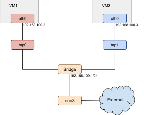
In this example, eth0 is created as the virtual network device for VM1, its host network backend is tap0. VM1 can access the host and the external network by the bridge.
OSC/bare-metal network
OSC/bare-metal adds a VM layer to the pod. Its network solution includes both the pod network and the VM network previously described:
- The virtual network and a tap device are created for the Kata pod VM.
- The veth pair is created for the pod.
Besides these devices, there are two key points in the network solution:
- Traffic Control (TC) filter is used between the veth device in the pod network namespace and the host tap device. With TC filter rules in place, a redirection exists between the container network and the virtual machine.
- Attributes of the VM virtual network device are the same as the attributes of the veth device in the pod network namespace. Before the VM boots, the Kubernetes network plugin places the veth device in the pod network namespace. Next, the Kata runtime scans the devices in the pod network namespace and gets the veth device. The Kata runtime attaches this veth device to the virtual machine and starts it.
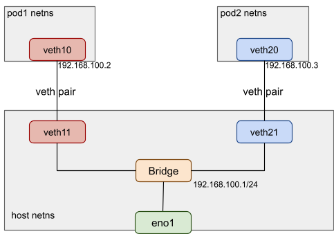
The image below describes the Kata container network topology:

In this example, a veth pair is created for each pod (VM). The veth11 device is in the default host network namespace. The eth0 device is in the pod1 network namespace. It is assigned the IP address 192.168.100.2 and MAC address be:65:4d:6e:0a:08. A tap device called tap0_kata and a virtual network device called eth0 are created for the pod VM. The virtual network device eth0 has the same MAC and IP address as the veth device, which is also called eth0 in the pod1 network namespace. A TC redirection filter is set up to mirror traffic from the pod1 netns eth0 ingress to the tap0_kata egress. A second mirrors traffic from the tap0_kata ingress to the pod1 netns eth0 egress.
OSC/peer-pods network
As previously mentioned, OSC/bare-metal uses the kata local hypervisor, while OSC/peer-pods uses the kata remote hypervisor. The main difference between the two regarding the network components is TAP vs VXLAN.
Instead of using a tap device for the pod VM, which could only connect to the local worker node, OSC/peer-pods creates a VXLAN tunnel to connect the worker node to the external pod VM.
The following is a brief introduction to VXLAN:
- Virtual eXtensible Local Area Network (VXLAN) encapsulates a Layer 2 Ethernet frame into a UDP packet and transmits it over a Layer 3 network.
- It establishes a logical tunnel on the IP network between the source and destination network devices to encapsulate user-side packets and forward them through the tunnel.
- If the IP addresses between servers are reachable, VXLAN can be used to build an overlay network.
In the OCS/peer-pods case, the worker node and pod VM can only connect to each other using IP addresses provided by the cloud provider (or third party hypervisors). Thus, a VXLAN tunnel must be created between them to establish connectivity.
The creation of the OSC/peer-pods networking infrastructure is described below:
- It starts with the creation of a veth pair. One veth device is in the host network namespace, the other device is in the pod network namespace.
- The remote hypervisor implementation (cloud-api-adaptor) creates a VXLAN device in the worker node and uses the pod VM's IP address as its remote destination IP address.
- The other end of the VXLAN tunnel inside the VM is set up by agent-protocol-forwarder. It uses the worker node's IP address as its remote destination IP address.
- A TC filter connects the veth device in the pod network namespace and the VXLAN endpoint in the worker node.
- With TC filter rules in place, a redirection is created between the container network and the VXLAN tunnel.
The following diagram shows the OSC/peer-pods network topology:

In this example, the worker node has a physical (or virtual) device eno1, and the pod VM has a physical (or virtual) device eno2. They are accessible to each other. A VXLAN tunnel is created between the worker node and the external pod VM. The VXLAN endpoint uses the physical device eno1/eno2 for the tunnel endpoint communication. Both VXLAN endpoints set the same VXLAN ID (such as 1024) and tagged remote IP addresses as the other side. The VXLAN endpoint in the worker node sets PodVM1's eno2 IP address 192.168.100.2 as its remote IP address. The VXLAN endpoint inside the pod VM sets the IP address 192.168.100.1 of the worker node's eno1 as its remote IP address. The veth pair is still created. One veth device is in the host network namespace, and the other is in the pod network namespace.
Note that the attributes (MAC address, IP address, etc.) of the veth device in the pod network namespace are the same as the attributes of the VXLAN endpoint inside the pod VM.
Guest image analysis
VMs are launched as the extra VM layer for the Kata containers and peer-pods Kata containers; however, the guest image of the VMs are different.
|
OSC/bare-metal |
OSC/peer-pods |
|
|
Guest image |
A VM image containing the same kernel as the host and the necessary initrd is transparently built when booting the host. As a result, in OSC/bare-metal, the guest kernel is always the same as the host kernel. |
A full disk image (such as qcow2) must be provided that contains the required kernel and initrd. In the long term, the necessary images should be provided by Red Hat. |
When starting OSC/bare-metal, a Linux kernel and a customized initrd image become the default image, and the versions are the same as the host operating system.
For example, the worker node host version is 5.14.0-284.18.1.el9_2.x86_64. The OSC/bare-metal VM is launched with -kernel /usr/lib/modules/5.14.0-284.18.1.el9_2.x86_64/vmlinuz and -initrd /var/cache/kata-containers/osbuilder-images/5.14.0-284.18.1.el9_2.x86_64/"rhcos"-kata-5.14.0-284.18.1.el9_2.x86_64.initrd.
The Linux kernel is the same as the worker node and boots a VM that is optimized for shorter boot time and minimal memory footprint. The initrd provides only the services required by a container workload.
The initrd image is a compressed cpio archive created from a rootfs, which is loaded into memory and used as part of the Linux startup process. During startup, the kernel unpacks it into a special instance of a tmpfs mount that becomes the initial root filesystem. Finally, the root filesystem switches to the virtio-fs.
When starting OSC/peer-pods, a full disk image (such as qcow2) is needed. It contains a full filesystem that is used by the VM, including the required kernel, initrd, and necessary services to create the environment to host the container. Neither the guest OS nor the guest kernel needs to be the same as the host operating system. The necessary images should be provided by Red Hat.
Wrap up
This blog compared OSC/bare-metal and OSC/peer-pods from three perspectives: deployment, component, and virtualization. The virtualization section analyzed the CPU, memory, storage, network, and guest image.
Hopefully, this article helped explain the differences between using OSC/bare-metal and OSC/peer-pods solutions.
Sobre los autores

Pei Zhang is a quality engineer in Red Hat since 2015. She has made testing contributions to NFV Virt, Virtual Network, SR-IOV, KVM-RT features. She is working on the Red Hat OpenShift sandboxed containers project.
Más similar
Navegar por canal

Automatización
Las últimas novedades en la automatización de la TI para los equipos, la tecnología y los entornos

Inteligencia artificial
Descubra las actualizaciones en las plataformas que permiten a los clientes ejecutar cargas de trabajo de inteligecia artificial en cualquier lugar

Nube híbrida abierta
Vea como construimos un futuro flexible con la nube híbrida

Seguridad
Vea las últimas novedades sobre cómo reducimos los riesgos en entornos y tecnologías

Edge computing
Conozca las actualizaciones en las plataformas que simplifican las operaciones en el edge

Infraestructura
Vea las últimas novedades sobre la plataforma Linux empresarial líder en el mundo

Aplicaciones
Conozca nuestras soluciones para abordar los desafíos más complejos de las aplicaciones

Programas originales
Vea historias divertidas de creadores y líderes en tecnología empresarial
Productos
- Red Hat Enterprise Linux
- Red Hat OpenShift
- Red Hat Ansible Automation Platform
- Servicios de nube
- Ver todos los productos
Herramientas
- Training y Certificación
- Mi cuenta
- Soporte al cliente
- Recursos para desarrolladores
- Busque un partner
- Red Hat Ecosystem Catalog
- Calculador de valor Red Hat
- Documentación
Realice pruebas, compras y ventas
Comunicarse
- Comuníquese con la oficina de ventas
- Comuníquese con el servicio al cliente
- Comuníquese con Red Hat Training
- Redes sociales
Acerca de Red Hat
Somos el proveedor líder a nivel mundial de soluciones empresariales de código abierto, incluyendo Linux, cloud, contenedores y Kubernetes. Ofrecemos soluciones reforzadas, las cuales permiten que las empresas trabajen en distintas plataformas y entornos con facilidad, desde el centro de datos principal hasta el extremo de la red.
Seleccionar idioma
Red Hat legal and privacy links
- Acerca de Red Hat
- Oportunidades de empleo
- Eventos
- Sedes
- Póngase en contacto con Red Hat
- Blog de Red Hat
- Diversidad, igualdad e inclusión
- Cool Stuff Store
- Red Hat Summit